Tuesday, November 7, 2023

Building the Didi 120 "Passion XI" - Finishing the Hull

David Edmiston, amateur builder of the Didi 120 “Passion XI”, is getting as much of the work done as he can while the hull is upside-down. Each time that I have turned the hull of one of my own big boat build projects it has rained the next day, turning my hull into a paddling pool. That possibility encourages a builder who doesn’t have a workshop large enough to house the new build to do much work that might otherwise have been left for when the boat was upright. I once visited a builder of a Didi 34, with the hull still inverted. He had the interior almost fully complete, including all painting, trims varnished and locker and cabin doors varnished and hung. All of that work had been done by a meticulous builder to a standard that few can achieve.

David is also doing some of the work needed for mechanical systems in his boat. Photo numbering continues from my previous post about this project.

Photo 35. The propeller shaft must be accurately aligned with the output shaft of the gearbox on the inside of the boat and the bearing of the P-bracket on the outside. In practice, the motor/gearbox, hole through the hull and the P-bracket are all aligned with each other and each can be fine-tuned during final installation to ensure proper alignment. Inaccurate alignment can create future problems over the life of the boat. In this photo, the hole through the hull has been bored and a wooden dowel of the same size as the shaft is being used to guide the work. The P-bracket is lying on the hull.


Photo 36. The hole through the hull has been enlarged to suit the fibreglass stern tube and the P-bracket has been wedged at the height and angle need to align with the shaft. The dowel is fitted through the cutless bearings of the stern tube and P-bracket exactly as the final shaft will be. The P-bracket has wooden wedges securing it at the correct height and angle for least binding of the dowel in the bearing. If the stainless steel shaft is available then it can be used instead of the dowel but the light weight of the dowel makes it much easier to work with. The dowel must be truly straight and round or accuracy will be sacrificed.


Photo 37. The stern tube and P-bracket have now been bonded into the hull with filled epoxy. The stainless steel shaft is now being used to ensure absolute accuracy of the installation. 


Photo 38. This shows the installation of the P-bracket on the inside of the hull. A plywood gusset has been glassed into the hull, making a solid mounting that is braced by the bulkhead. The P-bracket has been trimmed to remove unneeded length and bolted to the gusset. The hole through the hull is cut slightly over-size so that the P-bracket can align itself precisely with the shaft, with the epoxy filler taking up the slight slack.


Photo 39. The engine end of the shaft has been accurately set up on a board that is bolted to the engine bearers to coincide with the intended output shaft alignment, both in height and angle from horizontal. In this design, the stern tube is long enough to pass through and be bonded into a hull frame for long-term rigidity. This area of the hull has been made very rigid by extending the engine beds aft as girders to minimise hull flex in a part of the hull that might otherwise bend under heavy backstay tension.


Photo 40. The rudder shaft has been fabricated by an engineering company. It is stainless steel round bar of maximum thickness where it passes through the bearings in the hull bottom and is tapered both ends. The top end is also machined with a keyway to receive hardware for tiller and a radial drive wheel that will be used for connecting the autopilot. The latter can also be used to connect wheel steering for owners who prefer a wheel to a tiller. The flat bar tangs transfer the loads between the shaft and blade, which will be built over the shaft assembly.


Photo 41. The hole for the fibreglass rudder port has been cut through the bottom of the hull and the port dry-fitted in place for setting up accurate shaft alignment. The rudder will turn in acetal bushings that are fitted into the port and the fitting through the cockpit sole. Without that upper bearing to ensure accuracy of alignment of the rudder port, so this is done with temporary framing and clamps, seen at the bottom of the photo.


Photo 42. The rudder shaft has been suspended at the correct level to allow checking of all machining.


Photo 43. The rudder port is braced on the inside with plywood gussets fore/aft on centreline and transverse. The fore/aft gussets land on the backbone and the transverse gussets land on plywood doublers that reinforce the bottom plywood. The gussets are glassed over, with the glass extending onto all adjacent structures, making a strong and rigid structure to contain the loads applied by the rudder.


Photo 44. With the rudder port, stern tube, P-bracket and keel shoe installed, it is back to the outside to complete the hull. The glass reinforcement of the centreline has been laminated, tying the two bottom panels together. The glass is also worked over the keel shoe and onto the stern tube and P-bracket to further bond these to the wooden structure.


Photo 45. The wood surfaces have been prepared for finishing by filling any imperfections, fairing and sealing with epoxy. The light layer of fibreglass in the epoxy coatings is not structurally required but toughens the surface against light damage.


Photo 46. The aft end of the hull has received careful treatment. A sharp corner on a wood surface doesn’t hold finishes well and is easily damaged, with the potential for water to enter through unseen damage. This corner has been rounded to a radius that will hold the finishes and allows the bottom glass to be wrapped onto the transom. The corner is then built back to a sharp edge with reinforced epoxy to create a much tougher corner. There is good reason for this. Water flowing off the bottom at low speed hangs onto the surface and is dragged around the corner, with that water bubbling along behind the boat when it need not be there. A sharp corner encourages the water to break away to make a cleaner wake, with less drag.

Photo 47. After completion of the epoxy coatings and final fairing, primer coats have been applied, followed by topside paint and the bootstripe.


Photo 48. Fitting out and painting the interior has continued whenever weather conditions prevent work being done on the outside. Here is owner and amateur builder David Edmiston wielding his paint brush on aft cabin cave lockers.

The next post in this series will cover hull turning and the start of deck construction.

For information about our designs, please visit our Dudley Dix Yacht Design for our main website or our mobile site.

Monday, September 4, 2023

DH550 "Friends Forever" Finds New Friends

 JJ Provoyeur and Richard Bertie, with a team of artisans, built the DH550 "Friends Forever" on a golf estate in Devon Valley, near Cape Town South Africa. She travelled on a boat transporter along 30 miles of country roads and highways to her launch at Royal Cape Yacht Club, into Cape Town Docks.

Richard "Thirsty" Bertie with "Friends Forever" as she nears completion.

Loaded and ready for the road. A very wide load.

Under the gantry crane at Royal cape Yacht Club.
After launch parties and sea trials on Table Bay, "Friends Forever" went cruising, with JJ and friends aboard. After crossing the Atlantic Ocean to cruise the Caribbean, she crossed again to cruise the Med from West to East, then back again, ending up in Spain.
Sea Trials on Table Bay.
"Friends Forever" has recently been sold and was sailed by JJ Provoyeur and his friend Alexandre Monat across the Atlantic again. She is now in Edenton, North Carolina, for some modifications to her interior layout to better suit the needs of her new owners, who plan to live aboard and need office space for their online businesses.

I met "Friends Forever" when she arrived in Edenton and was pleased to meet up again with JJ, who I last saw nearly 10 years ago. It was great to have the opportunity to reconnect and I invited JJ and Alex to spend the night with Dehlia and myself in our home in Virginia Beach.
Chatting with JJ in the family room of our home, surrounded by boating memorabilia.
Next morning our two guests were to travel by Amtrak train to spend a day in Washington DC before flying off, JJ to Portugal and Alex to Cape Town. We have a nice photo of "Black Cat" in our entrance hall and Alex, A Frenchman living in Cape Town, asked for a photo of the three of us with "Black Cat".
"Black Cat" and friends.
JJ and Alex, thank you for visiting us. And "Friends Forever", I hope that you will be happy with your new owners.

For information about our designs, please visit our Dudley Dix Yacht Design for our main website or our mobile site.
 

Sunday, August 20, 2023

Building the Didi 120 “Passion XI”- Hull Skin

This is the 4th of a series of posts that follow David Edmiston's build of the prototype of the Didi 120. To follow the series, start with "Didi 120, Bringing the Didi 38 into 2022", then follow through chronologically. This post shows preparation for and fitting the hull skin. This changes the skeletal framework into what looks like a boat.

Photo numbering continues sequentially from post to post.

Photo 22. This view of the bottom structure of the hull shows the keel support grid, comprising backbone and keel floors. All have to be shaped by means of planes and belt sanders to form a fair surface for the plywood sheets to lie on, with contact with all surfaces to which they will be glued. This includes forming the dihedral (V-shape) onto the keel timber, which can be seen as having a peak on centreline. A guide for planing is created by using a long hand saw to cut into the backbone at each bulkhead, cutting down until the saw teeth just touch the edge of the bulkhead. The saw-cuts from the two sides will meet on centreline of the keel timber and planing down to the bottoms of those saw-cuts creates the required V-shape. Between bulkheads, the keel floors, stringers and tangent stringer can be used in the same way with the saw to make guide cuts. Limber holes run through all solid timber alongside stringers etc. to lead bilge water to the low points, where the bilge pump strum boxes will be. These openings must all be sealed either with multiple coats of epoxy or ¼ sections of PVC or GRP pipe bedded in epoxy. If you are wondering what the blue patches are in the limber holes, as I did when I saw them, they are reflections of the blue sky above in the gloss surfaces of the epoxy coatings.

Photo 23. The cockpit sole and seat fronts have been installed at a convenient stage of the assembly of the skeleton and is bonded to the bulkheads. The cockpit increases the rigidity of the structure to help it to hold shape during construction, helping to resist the forces applied by the multiple longitudinal timbers that are all pulling in different directions. It is also much easier to finish these surfaces and radius the corners with a router when working down-hand with the boat upside down, rather than working above you with dust and shards flying in tight areas when the boat is upright.

Photo 24. This is the opposite view to Photo 23, looking at the inside of the upside-down cockpit. The sole is supported by the triangular fillets at the edges. Triangular foot braces will be fitted to the top of the sole to assist with secure footing when well-heeled, serving also as stringers to stiffen the sole. This keeps the underside of the sole clean and flat, without head-bumping framing over the aft berth.

Photo 25. Much of the interior joinery can be built before the skin is fitted. The settee front and top can be seen at the top of the photo. Below that are the shelves that will be behind the backrest of the settee. Fitting them before the skin is fitted is quicker and easier than doing it later in the upright hull and the dust and shavings fall onto the ground instead of having to be vacuumed out of the nooks and crannies inside the boat. If fitted into a skinned hull, the edges of shelves and divisions must be carefully cut to fit against the skin. If fitted first they can be cut a few mm over-size, then easily planed back to the correct line for a good fit. It is a bit awkward to fit the shelves, fastening them with temporary panel pins to the triangular fillets, working upside-down. But it is well-worth the effort to do it this way.


Photo 26. This is how the interior looks when ready for the skin to be fitted. This is looking aft through the galley and nav areas toward the aft cabins and companionway from the front of the saloon.

Photo 27. The first of the bottom skin panels fitted in the bow. There are various ways to join the plywood panels together, including butt joints with butt blocks, scarf joints, jigsaw joints or butt joints with glass tape both sides. The builder has used butt joints glassed both sides for the bottom panels, so the ends of the panels are left square. For scarf joints the ends of the panels would be tapered over the last approx. 100mm before fitting, with the opposite taper planed onto the next panel. The outer longitudinal edges land on the tangent stringers, which have plywood doublers over which the junction between flat and radiused hull skin is formed. The centreline joint will be glassed over, after first being planed down a small amount to compensate for the added thickness of the glass layers.


Photo 28. The side and bottom panels have been completed, leaving the radius still to do. This is looking into the water tanks under the settees, for which all joints must be totally watertight. It is easiest to seal as many of those joints from outside as possible before doing the radius skin rather than trying to do them through the hatch openings after the completion of the skin. The edges of the side and bottom panels have been rebated half the thickness of the plywood. The first layer of the radius fits between the sheet edges and the second layer fits into the rebate.

Photo 29. The first layer of the radius is being fitted. It is done in vertical strips approx. 300mm wide (1/8 of the sheet length), which are spiled (shaped) at their meeting edges to form a close fit. The radius is tight in the bow and gradually opens up throughout the length of the hull, with this large radius aft for a powerful stern with a clean wake. The strips are cut with the surface veneer running fore/aft because the radius becomes too tight further forward for strips with the grain running the other way to conform to the curve.

Photo 30. The second layer of the radius is being fitted, set at an angle to the first layer. The builder is using screws through temporary wood strip doublers at the ends of the strips to pull them in, flattening out the slight bulges that can occur from fastening with screws alone. 

Photo 31. Both layers of the radius skin have been completed and fairing has started. The bow is finished with a hardwood stem that is built up in layers onto the front of the small bow bulkhead, then shaped to a rounded bow. This is fine at waterline for wave penetration and broad at deck level to increase flare in the topsides for reserve buoyancy.

Photo 32. The Ballast keel bears onto a dense hardwood shoe that forms a base on the bottom of the hull, to transfer the loads into the hull structure without risk of crushing the softer plywood skin. Here the shoe is being test fitted onto the flat surface that has been planed onto the hull to receive it and to which it will be glued after a layer of glass is laminated onto the hull. Both hull and shoe have been drilled with pilot holes for the keel bolts.


Photo 33. Fairing of the radius has been completed. The hull skin and stringers have been trimmed back to the final slope at the stern and the boarding step has been built, which creates a sealed void aft of the transom. The exposed areas of the inner face of the hull aft of the transom will be closed with a layer of thin plywood fitted over the stringers, with a timber capping closing in the aft end, creating more sealed voids. All surfaces of the hull and deck must be sealed with multiple coats of epoxy to prevent moisture penetration over time. Sealed voids and areas that will be difficult to access later during the build must not be forgotten because those are areas susceptible to problems in the future.


Photo 34. With the hull now closed in and forming a roof over itself, there is plenty that can be done inside the hull to keep the progress going when the weather is not playing nice. This photo shows the forepeak, with the epoxy coatings and painting done. The same has been done in the forecabin, from the sheer clamp to the upper tangent stringer and the structure of the forward berth has been built, as well as the fixed portion of the berth top. The open section of the berth top will be loose for access to the stowage below. The anchor locker has also been built in the forepeak, with the locker bottom and its two transverse stiffeners visible through the bulkhead opening. The bulkheads have unpainted stripes on centreline because the centreline that was drawn onto the plywood, when the bulkheads were made, is needed as a reference point throughout construction.

The next post in the series about this build will cover exterior coatings on the hull and installing the stern tube for the propeller shaft and the port for the rudder shaft.


Thursday, August 10, 2023

Explorer 18 Lapstrake Plywood Day-Sailer & Camp-Cruiser

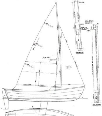
 I designed the Explorer 18 for Sentinel Boats in Cape Town, South Africa, for series production in fibreglass, from moulds. The plug from which the moulds were made was built from plywood and until now that is the only plywood one that exists. All of the drawings were for the GRP construction method. I have now detailed this design for building from plywood, with build methods suitable for amateur builders. It is fairly standard lapstrake plywood detailing with fibreglass tape to reinforce the longitudinal joints between panels.

This boat is a very capable family day-sailer, able to carry mom, dad and a few kids together. It has a secondary role as a camp-cruiser, with the 9ft long cockpit able to sleep the tallest of adults, with kids sleeping on the side seats.


The spaces under the seats are broken into nine separate buoyancy compartments, which can be accessed via waterproof covers for secure dry stowage.


The rig is gunter in sloop format, with mainsail and jib. The mainsail has a large foot batten instead of a boom, in the interests of saving heads from damage in unintended gybes.

The original GRP drawings were all hand-drawn, before the advent of CAD. Those drawings still form part of the plan set for the plywood version but are augmented by new details that have been drawn in CAD. A plywood components kit will soon be available, cut by CNC with jigsaw joints for panels that are longer than a plywood sheet length.

Click for more information for desktop or mobile.


Friday, July 21, 2023

Building the Didi 120 "Passion XI" - Keel Support Grid

This is the 3rd of a series of posts that follow David Edmiston's build of the prototype of the Didi 120. To follow the series, start with "Didi 120, Bringing the Didi 38 into 2022", then follow through chronologically. This post shows building the grid structure that supports the ballast keel and distributes the large loads that result from sailing in wild conditions and, if navigation is not as good as it should be, hitting the bottom.

Photo numbering continues sequentially from post to post.

Photo 12. The ballast keel loads are carried by laminated timber floors, which are beams that cross the bottom of the boat and pass through the centreline girder. The floor that aligns with the chainplate semi-bulkhead is being laminated in place against the backbone and stringers, from which it receives its shape. A host of clamps is needed to coax the layers of laminations into the required shape and squeeze excess glue out of multiple joints. The laminating is best done in stages because gluing all layers at once requires a lot of clamping pressure, which distorts the stringers outward, slightly flattening the shape of the floor from the desired curve. The post at left in the photo is a temporary support to hold the backbone at the correct height while the floors are being laminated.


Photo 13. The floors are in various stages of lamination and shaping. For the shorter floors, David chose to laminate a few layers on the hull longitudinals to lock in the basic shape, then to add layers as needed to build to the correct dimensions and to fine-tune the shape to an accurate fit against the longitudinals. The floors all taper in thickness towards the ends, so laminating is done with progressively shorter lengths of timber, then a belt sander is used to smooth them to the final shape. The hardwood shoe that will form the base on the outside of the hull for the ballast keel can be seen at the top of the photo.


Photo 14. The floors closest to the camera have still to be cleaned and trimmed to length. The others have been fine-tuned to shape and trimmed to length. The longest floor extends around the turn of the bilge at both ends. It aligns with the chainplate semi-bulkheads, to stiffen up this most heavily-loaded part of the hull that carries keel and rigging loads.


Photo 15. The floors have been glued in place to the longitudinals and the keel bolt holes have been drilled. Doublers are being glued to the forward faces of the floors to compensate for the timber removed in drilling the keel bolt holes. This doubler has been completed on the floor on the right and is being done to the other floors, using blocks and wedges to hold them in place while the glue cures. The floor on the left is the long one that connects with the chainplate bulkhead and will later be glassed to it. That junction is at the level of the settee top, which strengthens the junction as well. The settees are also structural, serving as girders to support the ends of the floors. The cleats that will bond the settee tops and fronts to the bulkheads can be seen on the two full bulkheads at the sides of the photo and the small semi-bulkhead in the centre. The tangent stringer can be seen on the other side of the hull, with the plywood doubler over which the junction between flat and radiused plywood panels will be formed.


Photo 16. This view shows the keel support structure clearly. This boat has a deep keel with very low CG, so the large loads applied to the hull require a very solid grid to distribute them away from the immediate area of the keel root. The floors and backbone structure do that work, with the floors carrying the transvers loads and the backbone carrying the longitudinal loads from groundings. He is starting to fill in the spaces between the longitudinals with timber glued to the floors. Limber holes will be formed through this timber filling to allow bilge water to get to the pumps.


Photo 17. These are the engine beds, which are formed from two layers of 12mm plywood. The aftmost laminated floor is located at the end of the girder and passes through the beds to link them, extending this strength member as a double girder through to the companionway bulkhead. Also passing through the beds, at left in the photo, is a sawn floor in two pieces, linking a pair of semi-bulkheads that are part of the aft cabin and heads compartment. At the midpoint of the floor is a laminated plywood connector bracket through which the stern tube and exhaust will pass and into which the front end of the stern tube will be bonded.


Photo 18. The centreline girder for this design is very solidly constructed to cope with the very large loads that potentially result from striking a rock with the toe of the keel. In this photo the spaces between the floors have been filled solid with timber, with the grain running fore/aft. The limber holes that can be seen running through the timber have been lined with ¼ sections of plastic pipe, set in epoxy, to seal the end grain of the timber. A boat with shallower and more lightly-loaded keel may have an H-section girder but the ISO calculations require this one to be solid timber.


Photo 19. The keelson is being dry-fitted as the final piece of the girder. It extends through the bulkheads at the ends of the saloon but is too long to be fed through them. It has a scarph to allow it to be fitted in two pieces with the scarph glued during fitting. The girder extends to the end of the walking area in the forecabin, picking up compression loads from the mast that are transmitted via the bulkhead in the right of the photo and the post that is glued to it.

Photo 20. The ends of the laminated floors extend through the settee fronts, which are structural, serving as deep girders and part of the keel support structure. The junctions between the floors and settee fronts are bonded with epoxy fillets.

Photo 21. The spaces under the settees are integral water tanks, so the junctions have to be waterproof as well as durable so that there is no future cracking to cause leaks. This is achieved with epoxy fillets reinforced with glass tape. This view is looking into one of the tanks through an access opening.


Diagram. Master section, showing details of hull and deck structure. Read along with the construction drawing in the previous post.

The next post about this build will be preparation for and fitting the hull skin.


Wednesday, July 12, 2023

Building the Didi 120 “Passion XI”- Bulkheads & Framing

The previous post, "Didi 120, Bringing the Didi 38 into 2022", described the development of the Didi 120 design from its predecessors in this design series, the Didi 38 and Didi 40cr. “Passion XI” is the working name of the prototype of the new design and is being built by amateur builder David Edmiston alongside his house in the suburbs of Sydney. We are going to follow his project, from the start through to completion, In a series of articles or photo essays. Thanks to David for providing the hi-res photos.

Although very modern in concept, this design uses a fairly traditional longitudinal girder backbone structure on centreline. This provides longitudinal stiffness to carry rig loads and resistance to grounding damage. It is combined with laminated transverse floors to carry keel loads and spread them into the rest of the hull. During construction, these structures, as well as a system of stringers and sheer clamp, are installed over bulkheads that are pre-cut to measurements and diagrams provided in the drawings and/or a table of offsets. This forms the skeleton to which the hull skin is fitted to complete the hull.

There are aspects of this project that are particular to the radius chine plywood method used for this design but overall the basic construction sequence and procedures are similar for most plywood boat projects. This series of photo-essays may help potential amateur boatbuilders to figure out whether or not a big boat project might be in their future, whether or not their skills and resources of time, money and endurance will see them through.

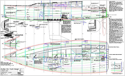
It can help with understanding the photos to refer to the drawings of this design in the previous post. The construction drawing shown here will clarify the basic construction layout. The plan view shows hull construction below centreline and deck construction above centreline. 

Photo 1.  Making bulkheads. The shapes are drawn onto the plywood from measurements on the table of offsets and diagrams on the drawings. The slots for stringers and backbone have been cut with a router and template for accurate placement of the longitudinals. The cordless drill gives scale to this large bulkhead, which is under the cockpit. It is cut from two sheets of plywood and scarphed at the joints. When built from a CNC kit the panels have jigsaw joints instead of scarphs. Other bulkheads are stacked against the wall in the background. The nearest bulkhead in the stack will be positioned mid-way along the forward berth. It has a laminated trim around the opening to soften the edge for any crew sleeping on that berth.

Photo 2. These bulkheads are ready for setting up. The cleats for joinery components are already glued on, ready to receive plywood fronts, tops and shelves. They are all located by measurements from centreline or waterline drawn onto the bulkheads. This reduces the time needed to build the interior joinery further into the project, while increasing the accuracy of setting out that joinery. The cleats are triangular in section, saving 50% of the weight compared with square cleats of equal size. Laminated roof beams have been fitted, holding the tops of the bulkheads securely at the correct widths. The surface has been primed with white epoxy primer to preserve it against weather during construction in an outdoor building site. Areas that will be glued or will be cut away later have been left unprimed. Also without primer are a narrow vertical stripe on centreline and a horizontal stripe low down on the bulkhead, where the centreline and design waterline (DWL) have been drawn and are needed for future reference. At the upper corners of each bulkhead, at the deck edge, large cleats have been glued on diagonally across the corner for gluing and screwing the sheer clamp. On these designs the sheer clamp sits diagonally across the corner to give a clean interior structure in that area and allowing a rounded deck edge on the outside.

Photo 3. This is the transom, with stiffeners and doublers glued on. It is about to be epoxy-coated and primed, so the blue painters’ tape is masking off areas where glue or epoxy fillets need adhesion onto raw timber. The stringers pass through the transom and will be epoxied in place. Short lengths of beige masking tape spaced around the perimeter show the locations of the hull and deck stringers, where the tape protects the gluing areas. The tape that protects the centreline marking is peeled back and the drawn centreline can be seen.

Photo 4. Setting up the bulkheads on the building stocks. Each bulkhead is bolted to two legs, which are themselves bolted to the rails of the building stocks. They must be set up vertical, at the correct fore/aft positions, centred and at the correct height, all within 1mm accuracy. This can be achieved by means of a plumb-bob hanging from a taut centreline string above the boat for vertical alignment and a laser level for height. This allows any bulkhead to be checked at any stage during setup, irrespective of other bulkheads. Alternatively, it can be done with a laser level that has both horizontal and vertical lines to check level and centring at the same time. For this method the bulkheads must be set up in sequence from one end of the boat to the other. The bulkheads must also be stabilized with bracing to hold them firmly until permanent longitudinal structure secures them. The fastenings must be bolts or large screws because they will eventually be carrying the full weight of the completed hull structure plus any people who may be working on top of the hull.

Photo 5. Stringers are set into slots in the edges of the bulkheads. Here they are being dry-fitted to the flat areas of the side and bottom panels to check for fairness of the stringer runs, also showing overall fairness of the hull shape. The area without stringers is the radiused portion of the hull. The backbone is also visible, being test-fitted on centreline.

Photo 6. The radius stringers have been added. The junction between flat and radiused hull skin is made with a plywood doubler fitted to the tangent stringer. What looks like a broad stringer is the plywood doubler over which the joint is made, with the tangent stringer under it.

Photo 7. The backbone is being dry-fitted to check for fit and curvature to where it must fit against the stem bulkhead. The backbone is too stiff to take the required curvature in the bow, so a horizontal saw-cut is made through the timber to allow it to be laminated in place. The large piece of plywood that looks like a longitudinal bulkhead is a temporary support for the stem bulkhead to hold it accurately in position. This boat has a plumb bow with the stem formed from a narrow bulkhead of multiple layers of plywood, with a solid timber nosecone bonded on later in the build process.

Photo 8. The backbone, stringers and tangent doublers have been glued to the bulkheads. The stringers will be trimmed off flush with the front face of the bulkhead before the nosecone is glued on. The backbone will be planed to a V-shape to match the dihedral angle of the bottom and that work has already started while fairing in the stringers against the sides of the backbone. The sheer clamps have also been fitted.

Photo 9. Side view of the same stage seen in Photo 8. The junction of the backbone with the stem bulkhead is made rigid and reinforced with a knee laminated from multiple layers of plywood. The knee is housed into grooves in the backbone and bulkhead. The stringer just above the tangent doubler has not yet been glued in place, it has been pulled into its correct position and secured with a rope to establish the alignment for planing the backbone dihedral angle in the forefoot area.

Photo 10. The chainplates of this design are inboard, i.e. they are bolted to a semi-bulkhead on each side, not to the hull skin. The loads are best transferred into the structure if those bulkheads align with the load direction. To do this, the bulkheads point toward the mast. In this photo David has the bulkhead clamped to temporary timbers that terminate at the mast support post on the major bulkhead. This boat has a deck-stepped mast standing on top of a reinforced bulkhead, which I have found from personal experience with my personal boats to be the best arrangement for a wooden boat. This places all of the structure under the mast in compression rather than having the compression loads on a keel-mounted mast foot attempting to force the backbone structure off the bulkhead, requiring stainless steel tie-bars to contain the loads.

Photo 11. Here the chainplate semi-bulkhead has been bonded to the stringers. The inner edges will be trimmed to final shape during fitting out of the interior. In this photo the sheer clamp can be seen, diagonal across the corner between hull and deck. The hull side skin has been fitted almost to the semi-bulkhead. The inner face of the tangent stringer can also be seen, with the narrow stringer projecting inward from the broader plywood doubler.

This build series will be continued in future posts, the frequency dependent on build progress.