The previous post, "Didi 120, Bringing the Didi 38 into 2022", described the development of the Didi 120 design from its predecessors in this design series, the Didi 38 and Didi 40cr. “Passion XI” is the working name of the prototype of the new design and is being built by amateur builder David Edmiston alongside his house in the suburbs of Sydney. We are going to follow his project, from the start through to completion, In a series of articles or photo essays. Thanks to David for providing the hi-res photos.
Although very modern in concept, this
design uses a fairly traditional longitudinal girder backbone structure on
centreline. This provides longitudinal stiffness to carry rig loads and
resistance to grounding damage. It is combined with laminated transverse floors
to carry keel loads and spread them into the rest of the hull. During
construction, these structures, as well as a system of stringers and sheer
clamp, are installed over bulkheads that are pre-cut to measurements and
diagrams provided in the drawings and/or a table of offsets. This forms the
skeleton to which the hull skin is fitted to complete the hull.
There are aspects of this project that are
particular to the radius chine plywood method used for this design but overall
the basic construction sequence and procedures are similar for most plywood
boat projects. This series of photo-essays may help potential amateur
boatbuilders to figure out whether or not a big boat project might be in their
future, whether or not their skills and resources of time, money and endurance will
see them through.
It can help with understanding the photos to refer to the drawings of this design in the previous post. The construction drawing shown here will clarify the basic construction layout. The plan view shows hull construction below centreline and deck construction above centreline.

Photo 1. Making bulkheads. The shapes are drawn onto
the plywood from measurements on the table of offsets and diagrams on the
drawings. The slots for stringers and backbone have been cut with a router and
template for accurate placement of the longitudinals. The cordless drill gives
scale to this large bulkhead, which is under the cockpit. It is cut from two
sheets of plywood and scarphed at the joints. When built from a CNC kit the
panels have jigsaw joints instead of scarphs. Other bulkheads are stacked
against the wall in the background. The nearest bulkhead in the stack will be
positioned mid-way along the forward berth. It has a laminated trim around the
opening to soften the edge for any crew sleeping on that berth.

Photo 2. These bulkheads are ready for setting up. The cleats for joinery components are already glued on, ready to receive plywood fronts, tops and shelves. They are all located by measurements from centreline or waterline drawn onto the bulkheads. This reduces the time needed to build the interior joinery further into the project, while increasing the accuracy of setting out that joinery. The cleats are triangular in section, saving 50% of the weight compared with square cleats of equal size. Laminated roof beams have been fitted, holding the tops of the bulkheads securely at the correct widths. The surface has been primed with white epoxy primer to preserve it against weather during construction in an outdoor building site. Areas that will be glued or will be cut away later have been left unprimed. Also without primer are a narrow vertical stripe on centreline and a horizontal stripe low down on the bulkhead, where the centreline and design waterline (DWL) have been drawn and are needed for future reference. At the upper corners of each bulkhead, at the deck edge, large cleats have been glued on diagonally across the corner for gluing and screwing the sheer clamp. On these designs the sheer clamp sits diagonally across the corner to give a clean interior structure in that area and allowing a rounded deck edge on the outside.

Photo 3. This is the transom, with stiffeners and doublers glued on. It is about to be epoxy-coated and primed, so the blue painters’ tape is masking off areas where glue or epoxy fillets need adhesion onto raw timber. The stringers pass through the transom and will be epoxied in place. Short lengths of beige masking tape spaced around the perimeter show the locations of the hull and deck stringers, where the tape protects the gluing areas. The tape that protects the centreline marking is peeled back and the drawn centreline can be seen.
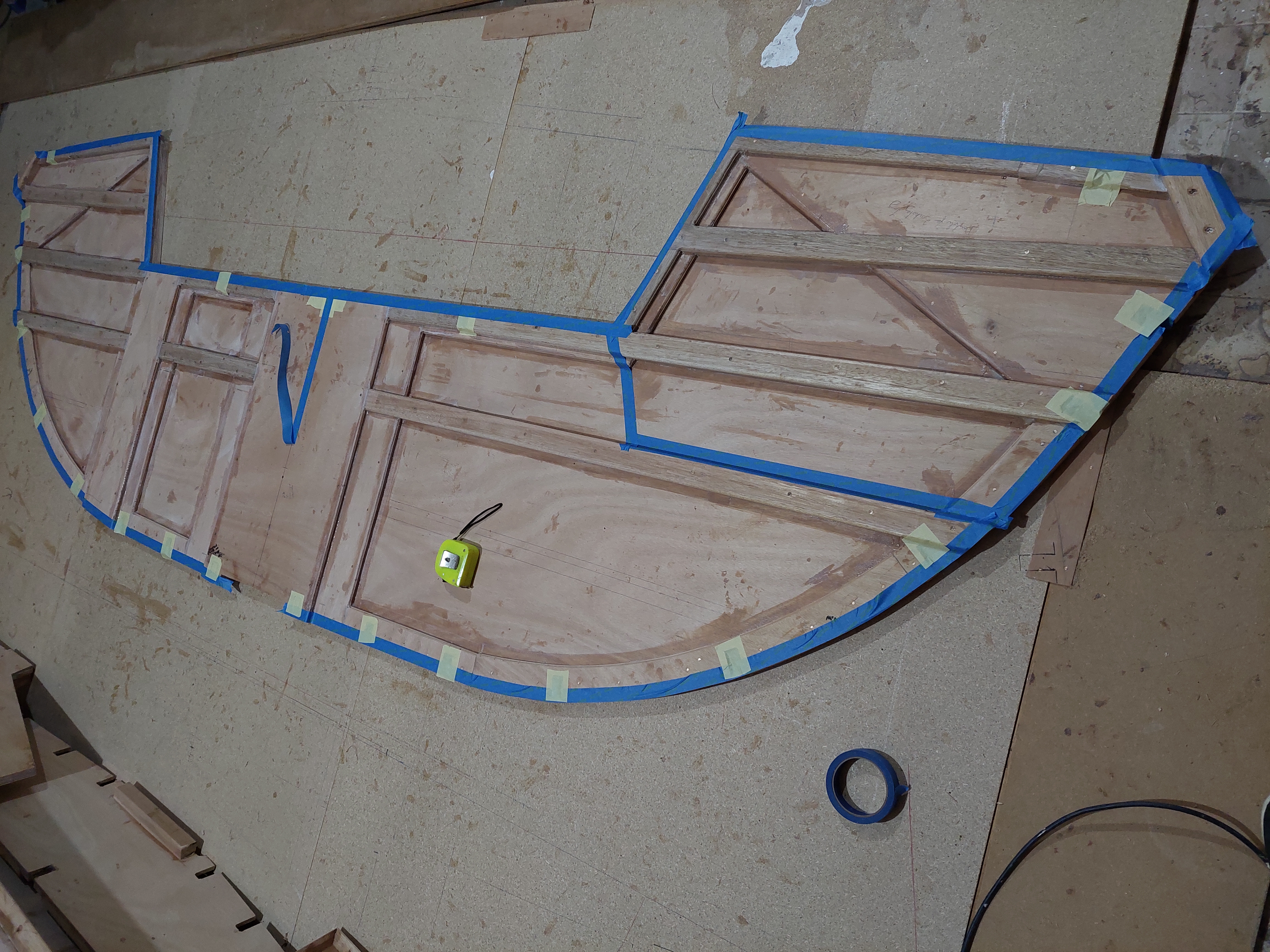
Photo 4. Setting up the bulkheads on the building stocks. Each bulkhead is bolted to two legs, which are themselves bolted to the rails of the building stocks. They must be set up vertical, at the correct fore/aft positions, centred and at the correct height, all within 1mm accuracy. This can be achieved by means of a plumb-bob hanging from a taut centreline string above the boat for vertical alignment and a laser level for height. This allows any bulkhead to be checked at any stage during setup, irrespective of other bulkheads. Alternatively, it can be done with a laser level that has both horizontal and vertical lines to check level and centring at the same time. For this method the bulkheads must be set up in sequence from one end of the boat to the other. The bulkheads must also be stabilized with bracing to hold them firmly until permanent longitudinal structure secures them. The fastenings must be bolts or large screws because they will eventually be carrying the full weight of the completed hull structure plus any people who may be working on top of the hull.

Photo 5. Stringers are set into slots in the edges of the bulkheads. Here they are being dry-fitted to the flat areas of the side and bottom panels to check for fairness of the stringer runs, also showing overall fairness of the hull shape. The area without stringers is the radiused portion of the hull. The backbone is also visible, being test-fitted on centreline.

Photo 6. The radius stringers have been added. The junction between flat and radiused hull skin is made with a plywood doubler fitted to the tangent stringer. What looks like a broad stringer is the plywood doubler over which the joint is made, with the tangent stringer under it.

Photo 7. The backbone is being dry-fitted to check for fit and curvature to where it must fit against the stem bulkhead. The backbone is too stiff to take the required curvature in the bow, so a horizontal saw-cut is made through the timber to allow it to be laminated in place. The large piece of plywood that looks like a longitudinal bulkhead is a temporary support for the stem bulkhead to hold it accurately in position. This boat has a plumb bow with the stem formed from a narrow bulkhead of multiple layers of plywood, with a solid timber nosecone bonded on later in the build process.

Photo 8. The backbone, stringers and tangent doublers have been glued to the bulkheads. The stringers will be trimmed off flush with the front face of the bulkhead before the nosecone is glued on. The backbone will be planed to a V-shape to match the dihedral angle of the bottom and that work has already started while fairing in the stringers against the sides of the backbone. The sheer clamps have also been fitted.

Photo 9. Side view of the same stage seen in Photo 8. The junction of the backbone with the stem bulkhead is made rigid and reinforced with a knee laminated from multiple layers of plywood. The knee is housed into grooves in the backbone and bulkhead. The stringer just above the tangent doubler has not yet been glued in place, it has been pulled into its correct position and secured with a rope to establish the alignment for planing the backbone dihedral angle in the forefoot area.

Photo 10. The chainplates of this design are inboard, i.e. they are bolted to a semi-bulkhead on each side, not to the hull skin. The loads are best transferred into the structure if those bulkheads align with the load direction. To do this, the bulkheads point toward the mast. In this photo David has the bulkhead clamped to temporary timbers that terminate at the mast support post on the major bulkhead. This boat has a deck-stepped mast standing on top of a reinforced bulkhead, which I have found from personal experience with my personal boats to be the best arrangement for a wooden boat. This places all of the structure under the mast in compression rather than having the compression loads on a keel-mounted mast foot attempting to force the backbone structure off the bulkhead, requiring stainless steel tie-bars to contain the loads.

Photo 11. Here the chainplate semi-bulkhead has been bonded to the stringers. The inner edges will be trimmed to final shape during fitting out of the interior. In this photo the sheer clamp can be seen, diagonal across the corner between hull and deck. The hull side skin has been fitted almost to the semi-bulkhead. The inner face of the tangent stringer can also be seen, with the narrow stringer projecting inward from the broader plywood doubler.

This build series will be continued in future posts, the frequency dependent on build progress.
No comments:
Post a Comment