In my
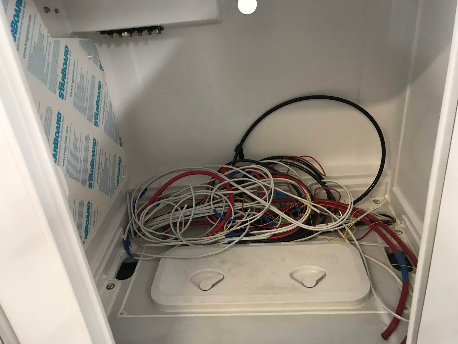
last post we had finished pulling cables and hoses through the ducts to their connection points. Most of the cables ended inside the console, coming up from the ducts under the deck. Also into this area came two hydraulic hoses for steering.
 |
| A mess of wires and hydraulic hoses, waiting to be connected. |
One side wall inside the console is given over to battery switches, breakers and busbars. These were pre-mounted onto a Starboard panel, then the panel was mounted into the console for wiring.
 |
| Battery switches, breakers, busbars etc being laid out on the Starboard panel before mounting in the console. |
`The main switch panel is mounted under a hinged cover on the outside of the console alongside the helm. This panel was pre-wired with the positive cables, ready for connecting to the power busbar and clearly labelled.
 |
| Switch panel pre-wired and ready for mounting in the console. |
With those panels in place, Kevin has been closeted inside the console making all of the connections. All connections are soldered then sealed with heat shrink tubing. All wires are clearly labeled with their purposes to help with later maintenance and fault-tracing.
 |
| Wiring in progress. The hole in the side of the console at bottom left below the panel connects to the mounting of the starboard forward leg of the tower. Controls for the crows nest helm will run up this leg and through the hardtop. |
 |
| Switch panel to the right of the helm, protected by the hinged cover. The ignition switch will be in the open space just to the left of the switch panel. Engine throttle and gearshift will be to the right of the helm. |
Making some of the hose connections to the tanks, seacocks and pumps can be challenging. Some of them are awkward to reach and to manipulate the hose, clamp and screwdriver one-handed. Long slim arms and supple hands are a big benefit.
 |
| This compartment contains the black water holding tank on the left and the fresh water tank on the right. The black fitting against the other side of the compartment is the Y-valve to control output from the holding tank to either the pump-out or the seacock. Inside this compartment there are five 32mm hose connections, two of 1" and two of 3/4". The order of connecting must be planned because some of the hoses block access to other fittings if done first. |
This design is not yet on our website. Visit our
main website or our
mobile website to see our other designs.


No comments:
Post a Comment