Showing posts with label amateur build boat plans. Show all posts

Thursday, November 22, 2018

Cuddy Cabin of Sportfisherman.

The cockpit deck of Kevin Agee's 26ft sportfisherman project is in and the insides of the hull sides have been glassed, soon to be faired ready for painting. The deck of the outboard engine bracket has been completed as well. I detailed the deck extensions of the bracket for wood construction but Kevin chose to do these with a Coosa board core between plywood top and bottom skins. The entire structure was glassed inside and out for longevity.
Outboard engine bracket structure has been completed and glassed. Glassing of the
transom is about to be done. The holes in the deck are for access to steering and
control cables and hoses.
Kevin was also working on hull framing, where I modified them to reduce the projection into the cockpit and increased their thickness to maintain strength. The only frame unchanged was at the boxings for the fuel filler pipes, which has to be large enough to contain pipes, vents and fittings.
Boxing for fuel filler being glued up. The next frame forward has been trimmed
and doublers added both sides, then glassed.
Boxing completed and glassed, ready to be trimmed flush with the sheer.
In the meantime I have been working on the cuddy cabin, fitting out the interior and preparing the deck framing.
Cuddy cabin sole dry-fitted, along with the pedestal for the toilet and the two
small shelf seats.
Kevin glued in the plywood soles and seats during the week before my next visit.
He epoxied bolts into the plywood to serve as studs to fasten down the toilet 
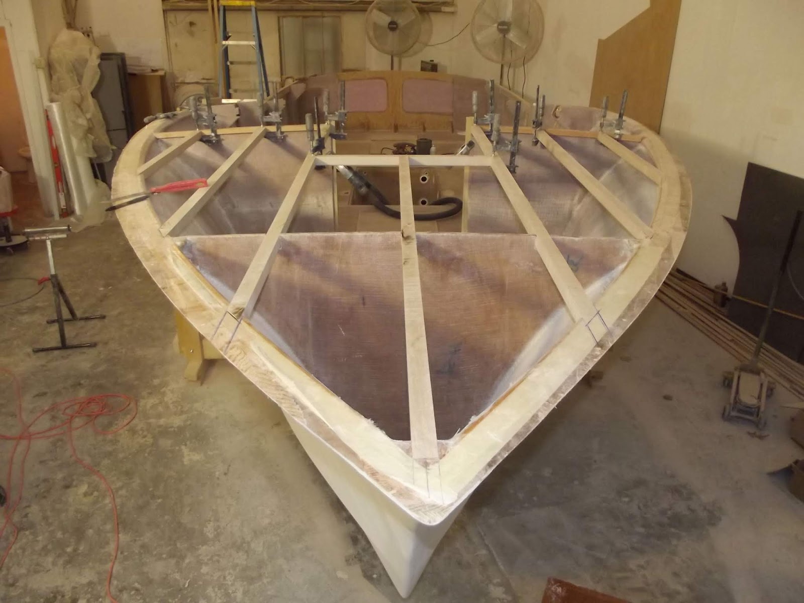
My next task has been framing the foredeck to get it ready for the plywood deck. Kevin has chosen to use curly maple for the deck stringers, which will be clear finished against the white-painted deck. The stringers run through the forward bulkhead and butt up against the aft bulkhead of the cuddy cabin, bonded to the bulkhead and cleat. The forward ends of the stringers are notched into the sheer clamp, which involves some careful setting out for cutting the slots and cutting the slots with a tenon saw and chisel.
Cutting a notch in the sheer clamp for a stringer. The length of wood is a straight-edge
to guide the angles of the saw. The back face of the notch is cut at about 45 degrees to
minimise the amount of sheer clamp that is cut away in the process.

Completed notches for deck stringers, through bulkheads and into sheer clamps.
Deck stringers and hatch trimmers dry-fitted and ready for gluing.
Deck stringers are notched into sheer clamps and bulkheads. They will be glued in
after the hull skin inside the cuddy cabin has been faired and sanded.
This build will be completed during the winter and launch is being planned for the spring.

This design is not yet on our website and will appear there closer to completion of Kevin's boat. To see our range of designs, go to our desktop website or our mobile website.

Tuesday, April 17, 2018

DH550 Charter Catamaran

The DH550 catamaran has been or is being built in the Caribbean, Europe, Africa and Australia. All of these builds have been to the original design, as drawn for Phil and Laura Harvey to build the prototype "Wild Vanilla" as a family cruiser.
"Wild Vanilla", now renamed "Taika" under her new owner
We now have a new version of the DH550 , named the DH550 Charter. It was commissioned by a charter company and construction will start in the next few weeks. It has features that are better suited to charter service, in the cabins, bridgedeck accommodations and rig.

This version has four equal double guest cabins, each with en-suite heads and shower. There is also a compact single crew cabin in the bows of each hull and a shared crew heads with shower in the starboard hull.

More space has been given over to life outside, so the bridgedeck accommodation has a smaller saloon and larger cockpit than the cruising version. It has two galleys, one internal and the other in the cockpit. The forward cockpit, a working area in the cruising version, is changed to a social area with seating and folding table. The working cockpit has moved aft to above the outside galley, with helm and engine controls. All sail control lines, except halliard and reefing lines, are led to a pair of electric winches mounted on the cabin roof. This cockpit has large cave lockers to keep the ropes tidy and out from underfoot.
DH550 Charter accommodation
The rig commissioned by my client has in-mast furling for easy handling. It has vertical battens to support modest roach.The boom has been raised for better clearance over the working cockpit. It has also been lengthened to regain some of the lost sail area and to move the sheet further aft to where it won't conflict with the working cockpit. A pair of posts has been added in the cockpit to pick up the loads applied to the cockpit roof by the mainsheet.
DH550 Charter rig with in-mast furling and vertical battens.
I also drew an alternative charter rig with slab reefing instead of in-mast furling. It regains area by means of more roach

Aesthetically, the charter and cruising versions are little different. The working cockpit is fairly inconspicuous, so doesn't spoil the clean lines of the cabin.

This version is only offered with cruising keels, for simplicity of operation. Lack of the daggerboard casings also gives more freedom for fitting in the required accommodation in the forward guest cabins.

The two steering stations are separate, connected only at the tillers on the rudder shafts, giving 100% redundancy. In the event of breaking a steering cable, the boat can still be steered at the other helm.

To see more of this and our other designs, go to our main website or our mobile website.

Monday, April 16, 2018

Glassing the Sportfisherman

Glassing of Kevin Agee's 26ft sportfisherman started yesterday, using WEST epoxy with a slow hardener to give ample time to do the work. We settled on a procedure that would give a surface that will need the least amount of fairing after completion of the glassing. That needed the glass fabric, 1708 biaxial glass with chopped strand mat on one side, to be laid down in a single length to eliminate transverse laps.

The procedure was to set up the roll of glass on a stand in front of the hull, then roll it out onto the bottom of the hull, cutting to size and shape. The 50" roll width was enough to cover one side from alongside the keel runner across to the chine, including the overlap onto the side. We cut two of these, one for each side, then rolled them up, ready for use.
Glass fabric laid out on hull and cut to shape.
The glass layer was to be covered by a layer of peel ply, so the order of tasks was to pre-coat the wood with epoxy in increments of approx 4ft, roll out the glass, wet-out the fabric with epoxy applied with mohair rollers, roll out the bubbles with ribbed rollers, lay peel ply over the top, squeegee smooth, then move on to the next 4ft section and repeat the process. The peel ply we laid in transverse strips so that we wouldn't be working with two rolls one behind the other to complicate the process.

Michelle mixed the epoxy, Kevin worked from the side on a ladder and I worked on top from the other side of centreline. We worked from transom through to the bow. About half-way through we realised that the planned completion of both sides of the bottom was not going to work. How was I going to work on top of the hull with fresh laminate where I had to stand? So the plan changed from doing two bottom panels in the day to doing one bottom panel and the opposite side, to remove any conflicts.
Half bottom glassed and covered with peel ply.
Glass wrapped onto transom. The glass roll on top of the engine bracket is for other bottom panel.
Two of Kevin's friends arrived to help after lunch, so we now had five working together to follow the same procedure. This was a big help because measuring out the glass for the side needed the glass to be held up against the hull, rather than calling on gravity to hold it there as we could with the bottom panel. The two new guys had done this work before, which none of the other three of us had done. They introduced the additional step of laying the glass back against the previous work to roll resin onto the contact surface of the new glass before it is pressed against the resin on the plywood, speeding up the wetting process.
Hull side glassed and covered with peel ply. It wraps across the chine flat and onto the bottom. When the second bottom is glassed there will be a double layer over the chine, a high-abrasion area that needs greater protection.
Side laminate wrapped onto transom. 
Other work that was done prior to starting the glassing was gluing the bottom panels onto the engine bracket, as well as structural epoxy fillets around the perimeter and inside the bracket. Some of this can be seen in the photo above.

The rest of the hull will be glassed over the next week.

This design is still not on our website, so there are no links to the design in this post. To see our range of designs go to our desktop website or our mobile website.

Saturday, February 24, 2018

Sportfisherman 26 - Let the Skin Begin

Since my last post on Kevin Agee's project the 2nd and 3rd layers of the sheer clamps have been laminated onto the first one, to take it up to its full size. These layers were easier to do because the first layer was already in place, defining the twist and giving a convenient surface for clamping. There was no need for a Spanish windlass to pull them in.
Second layer of sheer clamp glued and clamped.
The 2nd layer of the bottom skin has also been glued on. It is secured and pulled in tight with temporary screws and fender washers, working outward from the centre of each sheet toward the edges, forcing air and excess glue out at the edges. A boat like this will sometimes take some hard hits on the bottom when running into rough conditions, so bad lamination in the bottom must be avoided. The screws will be removed and the holes filled with epoxy, inserted with a syringe.
2nd Layer of the bottom glued and fastened with temporary screws and fender washers.
Time was approaching for the side skin to be started. This is being done in bead and cove cedar that was bought in 4" plank widths, then cut down to the desired widths on a table saw. After scarphing to the lengths needed to cover the hull in single lengths, they were run through the router on a router table to form the cove and bead. This was done with a crown molding #3 router bit, using the convex part of it for the cove and the concave part of it for the bead. The two fit together nicely for the bead and cove joint.
Crown molding #3 router bit sourced from Lee Valley.
Fit of the bead and cove strips cut with the router bit shown above.
With a large stock of newly-machined strips scarphed into long lengths and waiting on top of the hull, the pressure was on me to finish shaping the bevels on the stem to to the correct angles to receive the ends of the strips. This is done by holding (clamping if there aren't helping hands available) a strip against the sides of the bulkheads and frames, with the forward end in correct position to run fair into the stem and with the tip just short of the stem. Then a saw cut is made into the stem with the saw running against the upper face of the strip until the teeth are flush and parallel with the inner edge of the strip. This is repeated in a series of positions until representative cuts have been made the full length of the stem where it will be crossed by strips.
The stem is still rectangular in section but has saw cuts to show the bevel angle needed by the skin.
Next, the bulk of the timber is taken out with a chisel to give the rough surface , finished off to the final surface with a plane and/or a Shinto saw rasp.
Using a chisel to remove the bulk of the excess wood. This side of the stem proved tough to break out due to the grain direction, the other side came out much more cleanly. This side needed the Shinto saw rasp to finish it, whereas the other side came in nicely with a plane.
The completed stem bevels, ready for the bead and cove strips.
A decision has to be made by each boat builder where to place that first strip. Some like to start at the chine, then work toward the sheer. Others prefer to start at the sheer and work toward the chine. Still others will start somewhere between the two and work in both directions. This third option was our choice, mostly because the boat has a broken sheer that gives a convenient start line.

We started by clamping the strip with the lower edge flush with the lower edge of the straight aft sheer clamp. Forward of that aft sheer clamp, we slid the forward part of the strip up and down against the framing until we found the line that placed the least stress on the strip. In that position there is minimal force needed to pull the strip against the framing, so fitting is easy and the same should also be true for the rest of the skin.
The first strip glued flush along the lower edge of the aft sheer clamp and the forward part aligned for least stress in the timber.
Starting to look good, with six strips fitted. The strips are run past the ends of the hull, then trimmed back after the epoxy has set.
The strips are nailed to each other with plastic brads that are shot in with a pneumatic gun. Temporary screws and fender washers are holding them to the framing. Due to the low-stress alignment chosen for the strips, hand pressure was all that was needed to hold each strip against the previous one for fastening, no clamps were needed.
With much of the hull skinned both sides, time to stop. The chine flat must be built first from Douglas fir, then the side strips will be finished against the chine.
Scarph joints in the strips to make hull-length strips. The strips are positioned to spread the scarph joints out so that they are not all in the same place on the boat.
Building the chine step will be next, on the program for tomorrow.

This design is not yet complete, so is not on our pricelist or website. See previous posts on this blog about the 26ft Sportfisherman for more info. See our full range of designs on our main website or our mobile website.

Tuesday, January 30, 2018

Chine Stringers for Our Sportfisherman 26

Continuing with the 26ft sportfisherman project, the next step is to fit the chine stringers. This boat has a chine step that will be planked with Douglas fir strip. On the inboard edge of the step there is a stringer to support the outboard edge of the plywood bottom skin. These stringers fit into slots in the bulkheads and are housed at their ends into the transom and the stem.

That sounds like a simple process and for most of the hull length it is simple. Toward the bow it becomes more difficult because each stringer has to twist to follow the bottom panel and bend to follow the chine. It takes considerable power to pull that twist into the stringer as it goes into place.

The stringers also have to pass through the forward ends of the girders, with slots fashioned to fit the stinger path. The shapes of the slots through the girders are not easy to establish, so there is considerable work with saw, chisel and rasp to form the slots and filled epoxy is needed to fill in the inevitable gaps.

The end result is good. The photos and captions show the process.
The slots through which the stringer must pass on its way to the stem. The slot shape only applies on one surface of the bulkhead or girder, which must be used as a guide for shaping the bevel angles for the stringer through each member. In these photos the light coloured bulkheads are temporary formers, the darker ones are permanent and the horizontal members are the girders.
The slots through the temporary former and the girder have been shaped and the stringer is a reasonable fit. The upper edge of the girder will be bevelled to match the bottom skin, which will bring it into the same plane as the outer face of the stringer.
This photo shows how to establish the bevel shape of the stem to match the hull skin, also giving the front edge of the stringer when housed into the stem in the correct position. The stringer is now in the bulkhead slots but is short of the aft face of the stem, so it is lying at the correct angle relative to the stem. The saw is used to cut into the stem, down to the point that the saw teeth are touching the outer face of the stringer. The resulting saw cut is an extension of the line of the stringer.
The socket to receive the end of the stinger is easily made with a saw and a chisel. Housing it in like this is a stronger option than simply gluing and screwing to the side of the stem.
The socket for the aft end of the stringer in the transom is done in similar manner to the one in the stem. 
The stringer glued into its slots, passing through bulkheads and girders. The blue painters tape is there as a bond breaker to prevent adhesion where it is not wanted.
Here you can see how we pulled the twist into the stringers. We fitted the two in parallel, gluing both in the difficult twisted bow sections first before moving aft on one, then the other. The clamps are holding the twist in the forward ends, with the clamps lashed together with ropes pulled tight to provide the torque needed.
Stringers showing fair curves and securely lashed until the epoxy has fully cured.
The next stage of building will be to prepare the bottom framing to receive the bottom skin, by planing bevel angles on bulkheads, girders, keel and stem.

This design is not yet complete, so is not on our pricelist or website. See our full range of designs on our main website or our mobile website.

Thursday, September 1, 2016

Didi 26 Opportunity

Al Beyers was building his Didi 26 in Canada. It was to be for his own use for leisure sailing and sail training. Al succumbed to cancer before he completed the boat. The lady who inherited Al's boat needs to sell it urgently and is now offering it at a price that is well below the material cost. This is a great opportunity to acquire a fast trailer-sailer that has already had most of the building work done. I haven't seen her myself but she appears to have been nicely built.

She is slightly modified from our standard design, with the addition of a sugar scoop to the stern, water ballast tanks and tube for a below-decks retractable bowsprit. She still needs finishing trims for the woodwork to be completed and includes keel foil, rudder, unfinished ballast bulb, chemical toilet and trailer. She still needs rig, sails and hardware. More recent photos are available from the seller if you have serious interest in buying her.
Clean modern hull with high performance potential.
The bowsprit launch tube is non-standard but a practical solution.
Bow view. The cabin front end is a non-standard.
Sugar scoop stern with cut-out for transom-hung rudder.
Large racing cockpit
Inlay in cabin sole.
Quarter berths and companion ladder.
Lead ballast bulb halves.
Keel foil.
Forward berth.
On her trailer.
Her price is CAD5500. She can't be built to this stage for that price, so appears to offer a new owner a fast leg-up on getting a Didi 26 onto the water.

As usual, purchase of a boat like this should not be concluded without an in-depth inspection by an experienced boatbuilder or surveyor.

Contact me by email if you wan to follow up about this boat and I will put you in contact with the owner.

Dudley Dix

Thursday, July 21, 2016

Didi Sport 15 Adaptive - Sportboat for those with Handicaps

I have written in previous posts about the Didi Sport 15, aka the DS15. You can see one of those posts at this link or use the search window to view the many other posts.

This design caught the attention of two sailors in Santa Cruz, California. George Arthur and Luc de Faymoreau are involved with an accessible sailing program, helping sailors with disabilities to get afloat and sailing. They asked if it would be possible to redesign the DS15 to be suitable for disabled sailors and still have good performance.

The resulting design process has produced a specialised version of the DS15, using the same hull and foils as the base platform but with modified deck and sail plan. The name of the new design is the Didi Sport 15 Accessible, aka the DS15A. We don't yet have a design page for it on our website, that will come with time.
The DS15, basis for the new accessible boat
The deck modifications are to allow two sailors to sit in tandem in secure seats. The crew are seated in a narrower cockpit that allows them to brace themselves against solid structure when they feel the need, or to lean against something solid. The cockpit has low comfortable coamings that crew can hook an arm or an elbow onto, to hold themselves to windward if they want. Severely handicapped or weak crew can be strapped into the seats with harnesses if needed, to assure their safety.
3D Image of the DS15A accessible sportboat.
The rig has been reduced in power because the crew will not have the benefit of the stability advantages from mobile crew and single or twin trapezes. The ballast bulb on the daggerboard will be standard equipment rather than an optional item as with the DS15. It has a smaller asymmetrical spinnaker as well, on a shorter retractable bowsprit, for more advanced sailors in the program.
DS15A sail plan, reduced power but still exciting.
Sail controls are all led to the two seats, with camcleats on the sidedecks or cockpit sole, to share boat handling functions between skipper and crew. Some controls can be operated from either seat, to help with sail training or to better serve crew with different disabilities. Steering is by means of joysticks mounted in front of each seat, driving cables that are connected to the tiller.

This boat is not only for those with physical handicaps though. It is also well-suited to those who feel that they no longer have the agility or fast reactions demanded by a powerful boat like the standard DS15. It is also less intimidating to many wives and other less adventurous people who would still like to get out onto their local sailing waters with less fear that their thrill-seeking partners are going to scare the daylights out of them.

The first boat is about to start construction in Santa Cruz, being built from a plywood component kit, accurately cut by CNC router and shipped from our kit supplier on the East Coast. Construction is radiused chine plywood, giving a round bilge hull that is within the abilities of amateurs. From this first boat they will make moulds, whereafter fibreglass boats will be produced for the use of their own program and to fill orders from other programs and individuals.

We will also sell the design on the same basis as applies to the DS15, so it will be available as plans only, plans with full-size patterns or plans with a CNC kit.

I look forward to seeing the first of these versatile boats sailing. I will update progress with future posts on this blog.

To see our other designs, go to our desktop website or our mobile website.