Showing posts with label build a boat yourself. Show all posts

Friday, January 11, 2019

Didi 27 Retro

It has been a few years since we introduced the Didi 29 Retro, a gaff-rigged cruiser-racer based on our popular Didi 26 trailer-sailer sportboat. Bruce Mierke of North Carolina built his "Arabella" to this design with a modified (shorter) cabintop. Sisters are also being built in Africa, Europe, Asia and Australia.
Didi 29 Retro "Arabella", built by Bruce Mierke.
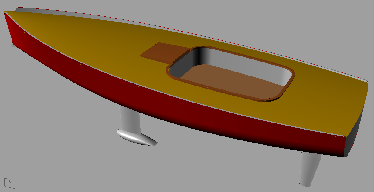
Inspired by "Arabella", another client commissioned a boat on the same basis but heading in a slightly different direction. The new boat is a classically-styled day-sailer with enough horsepower for exciting sailing.

The hull is based on the Didi 26, with some modifications. It has a plumb bow and aft the lines have been extended for a clean and powerful stern, ending in a radiused vertical transom. Along with that it has bulwarks forward, which taper aft into a normal toerail. The result is a more springy sheer curve.
Clean flush deck and centre cockpit
Bulwarks, bulb fin keel and spade rudder.
Being a dayboat, it has a clean flush deck with centre cockpit and no cabin structure. My client wanted only two settees down below with sitting headroom but I included a double forward berth to add the option of camp-cruising. A Porta-Potti and camp stove can be stowed under the cockpit and a boom tent can extend sleeping space to include the cockpit.
Powerful Marconi rig.
The rig is a powerful fractional Marconi sloop configuration, with square-head mainsail. The asymmetric spinnaker is flown off the end of a retracting and pivoting bowsprit. The deck-stepped mast is supported by double swept spreaders and there are also runners to help with the loads from the asymetrical in strong winds.
Camp-cruiser accommodation
My client wanted a fixed keel and a lifting keel will also be available. The foils are wood, sheathed in uni-directional glass, with a cast lead ballast bulb. The rudder is in a cassette that allows it to be lifted for servicing and for the lifting keel boats to get into shallow water.

We will be offering CNC kits for this boat, including the interior components. Plans are available immediately and kits in the near future.

To see our other designs, go to our main website or our mobile website.

Thursday, December 27, 2018

New Cape Henry 21 Launch in Australia

Ron Jesche in Adelaide, South Australia, has launched the newest build to our Cape Henry 21 design. Ron is a professional boatbuilder and owner of Stainless Boatworks. He produces high quality custom metal hardware for both power and sailing boats.

Ron bought the plans to build for his own use and has made a beautiful job of the build. He has enjoyed working with our well-detailed drawings so, part-way through the project, he took on the agency to sell our designs and plywood kits in Australia. He exhibited his nearly-complete boat at a local boat festival where it attracted considerable attention.

"Sealion" is finished in a very pretty blue, with cream decks. She was launched on Christmas Eve and went for her first sail on Christmas Day. Ron is delighted with the performance and good manners of his Christmas present to himself. His wife also enjoyed sailing on "Sealion" and feels safe on her, an important element of family boat enjoyment.

Ron's photos show what a great job he did of the build.
Nicely-detailed joinery for a pretty interior.
The work of a craftsman who is jusifiably proud of what he has produced.
Ron Jesche exhibiting "Sealion" at the boat festival.
Jon installed a small inboard diesel motor, tucked under the front of the cockpit.
Launch day, nearly ready to go sailing.
First sailing photos. Ron reported that she topped out at 5.8 knots in a 10 knot breeze.
Romping along under full cutter rig.
Ron's comments after sailing "Sealion"? What a great boat. Under 10 knots as we left and she sailed beautifully with jib and main, great steerage and control downwind in very light wind. As the wind picked up she accelerated beautifully. I am absolutely thrilled with this little boat, and can't wait to get out again tomorrow. I can't get over how well she sails. She heaves to very nicely also,and nicely mannered on all points of sail. 

Ron Jesche is well-qualified to represent us in Australia. He has general boatbuilding experience and also personal experience of building one of our most popular small cruisers, good qualities for advising potential builders about the build process and the quality of the designs that he represents. He can also supply kits for most of our plywood designs. Contact Ron via his website at Stainless Boatworks.

To date we have sold more than 100 sets of plans for the Cape Henry 21. To see our range of boat designs, go to our desktop website or our mobile website.

Thursday, November 22, 2018

Cuddy Cabin of Sportfisherman.

The cockpit deck of Kevin Agee's 26ft sportfisherman project is in and the insides of the hull sides have been glassed, soon to be faired ready for painting. The deck of the outboard engine bracket has been completed as well. I detailed the deck extensions of the bracket for wood construction but Kevin chose to do these with a Coosa board core between plywood top and bottom skins. The entire structure was glassed inside and out for longevity.
Outboard engine bracket structure has been completed and glassed. Glassing of the
transom is about to be done. The holes in the deck are for access to steering and
control cables and hoses.
Kevin was also working on hull framing, where I modified them to reduce the projection into the cockpit and increased their thickness to maintain strength. The only frame unchanged was at the boxings for the fuel filler pipes, which has to be large enough to contain pipes, vents and fittings.
Boxing for fuel filler being glued up. The next frame forward has been trimmed
and doublers added both sides, then glassed.
Boxing completed and glassed, ready to be trimmed flush with the sheer.
In the meantime I have been working on the cuddy cabin, fitting out the interior and preparing the deck framing.
Cuddy cabin sole dry-fitted, along with the pedestal for the toilet and the two
small shelf seats.
Kevin glued in the plywood soles and seats during the week before my next visit.
He epoxied bolts into the plywood to serve as studs to fasten down the toilet 
My next task has been framing the foredeck to get it ready for the plywood deck. Kevin has chosen to use curly maple for the deck stringers, which will be clear finished against the white-painted deck. The stringers run through the forward bulkhead and butt up against the aft bulkhead of the cuddy cabin, bonded to the bulkhead and cleat. The forward ends of the stringers are notched into the sheer clamp, which involves some careful setting out for cutting the slots and cutting the slots with a tenon saw and chisel.
Cutting a notch in the sheer clamp for a stringer. The length of wood is a straight-edge
to guide the angles of the saw. The back face of the notch is cut at about 45 degrees to
minimise the amount of sheer clamp that is cut away in the process.

Completed notches for deck stringers, through bulkheads and into sheer clamps.
Deck stringers and hatch trimmers dry-fitted and ready for gluing.
Deck stringers are notched into sheer clamps and bulkheads. They will be glued in
after the hull skin inside the cuddy cabin has been faired and sanded.
This build will be completed during the winter and launch is being planned for the spring.

This design is not yet on our website and will appear there closer to completion of Kevin's boat. To see our range of designs, go to our desktop website or our mobile website.

Wednesday, November 7, 2018

Didi 40cr Opportunity in New Zealand

The Didi 40cr is a variation of our Didi 38 design, of which my "Black Cat" was the prototype. We launched "Black Cat" in November 1995; she will be 23 years old in a few days and has crossed the South Atlantic 6 times. There are more then 80 sisters sailing or in build around the world.

A builder in Whangarei, New Zealand, has built his Didi 40cr hull to a good standard but is not able to carry on with it. He is relocating to UK and cannot take the boat with him. His project is available at no cost to another builder who would like to own and sail a fast cruiser/racer like this.

The hull structure is mostly completed, so will give a builder a head-start of 1000 or more hours in saved building time.
Most of hull structure completed.
Neatly executed woodwork.
The hull is still upside-down on its building stocks, mounted on a road trailer and protected from the weather by a tarp. The trailer is available to move the hull but must be returned to its owner.
Hull on building stocks, mounted on road trailer.
For more information on this opportunity, go to the listing at
https://www.trademe.co.nz/Browse/Listing.aspx?id=1812843342, from where you can contact the owner directly.

Thursday, August 16, 2018

Hout Bay 30 Cutter New Launch

Another boat to our designs has been launched in Russia. This one is a steel Hout Bay 30, built by Aleksander Kokorin of Kranoyarsk in Siberia. He launched into the Yenisei River, which is the largest river system flowing into the Arctic Ocean.

The Hout Bay 30 is a frameless design, so the hull is built over temporary frames that are removed at the time of turning the hull over. I have a few photos from the start of construction in 2009, then a big gap through to those at launch in 2018.
The temporary frames have been set up on the building stocks and the centreline stringer fitted.
The transom has been set up. The stringers will be tack-welded to the tabs that can be seen projecting from the frame edges.
Arriving at the launch ramp.
Setting up a bipod frame to raise the mast.
Boat afloat, mast in place and bipod ready to do its work.
And up it goes.
No sails yet but she looks very pretty in a beautiful setting.
See more of this and our other designs on our main website, or our mobile website.

Tuesday, January 30, 2018

Chine Stringers for Our Sportfisherman 26

Continuing with the 26ft sportfisherman project, the next step is to fit the chine stringers. This boat has a chine step that will be planked with Douglas fir strip. On the inboard edge of the step there is a stringer to support the outboard edge of the plywood bottom skin. These stringers fit into slots in the bulkheads and are housed at their ends into the transom and the stem.

That sounds like a simple process and for most of the hull length it is simple. Toward the bow it becomes more difficult because each stringer has to twist to follow the bottom panel and bend to follow the chine. It takes considerable power to pull that twist into the stringer as it goes into place.

The stringers also have to pass through the forward ends of the girders, with slots fashioned to fit the stinger path. The shapes of the slots through the girders are not easy to establish, so there is considerable work with saw, chisel and rasp to form the slots and filled epoxy is needed to fill in the inevitable gaps.

The end result is good. The photos and captions show the process.
The slots through which the stringer must pass on its way to the stem. The slot shape only applies on one surface of the bulkhead or girder, which must be used as a guide for shaping the bevel angles for the stringer through each member. In these photos the light coloured bulkheads are temporary formers, the darker ones are permanent and the horizontal members are the girders.
The slots through the temporary former and the girder have been shaped and the stringer is a reasonable fit. The upper edge of the girder will be bevelled to match the bottom skin, which will bring it into the same plane as the outer face of the stringer.
This photo shows how to establish the bevel shape of the stem to match the hull skin, also giving the front edge of the stringer when housed into the stem in the correct position. The stringer is now in the bulkhead slots but is short of the aft face of the stem, so it is lying at the correct angle relative to the stem. The saw is used to cut into the stem, down to the point that the saw teeth are touching the outer face of the stringer. The resulting saw cut is an extension of the line of the stringer.
The socket to receive the end of the stinger is easily made with a saw and a chisel. Housing it in like this is a stronger option than simply gluing and screwing to the side of the stem.
The socket for the aft end of the stringer in the transom is done in similar manner to the one in the stem. 
The stringer glued into its slots, passing through bulkheads and girders. The blue painters tape is there as a bond breaker to prevent adhesion where it is not wanted.
Here you can see how we pulled the twist into the stringers. We fitted the two in parallel, gluing both in the difficult twisted bow sections first before moving aft on one, then the other. The clamps are holding the twist in the forward ends, with the clamps lashed together with ropes pulled tight to provide the torque needed.
Stringers showing fair curves and securely lashed until the epoxy has fully cured.
The next stage of building will be to prepare the bottom framing to receive the bottom skin, by planing bevel angles on bulkheads, girders, keel and stem.

This design is not yet complete, so is not on our pricelist or website. See our full range of designs on our main website or our mobile website.

Tuesday, January 16, 2018

Installing the Sportfisherman Backbone

In my previous post Kevin laminated the keel and stem, the two components that make up the backbone of the new boat. Now we must shape the scarph joint that will combine them into one piece and then install them.

That introduces a tricky problem that may confound some builders who may not have done this before. The problem is that the keel and the stem have to both occupy the same space before the joint that bonds them together is shaped. This joint must be very carefully shaped to create an effective scarph joint with the two parts correctly aligned. Trying to do this by measurement has a pretty big chance of an error causing a mismatch, with a bad joint the result and possibly having to make a new stem or splice in an extension on the keel.
This photo shows the keel being laminated in position, extending to Frame 1. The frame that is in front of it is Frame 0, at the forward end of the design waterline (DWL). The stem has been made to extend from the tip of the bow, over Frames 0 and 1, ending at Frame 2. The overlap between the two allows us to blend them at the joint.
A template is needed to get the cut angle correct, with the template used first on the keel, then on the stem. But if we do that off the boat the chances are that we will get it slightly out of position or at slightly the wrong angle, yielding a bad scarph. A small difference in thickness between the keel and stem will throw out the angle substantially. To remove this considerably risk, the template needs to be on the hull framing and it must be done in a way that it can be used to mark the angle on the two components individually.

To accomplish this we needed three battens. These we set up with the keel in position and the ends of the desired scarph marked onto the top and bottom of the keel. Two of the battens are clamped against the frames, one on the aft face of Frame 1 and the other on the front face of Frame 2. Both are vertical and away from the side of the keel by the thickness of a batten. The third batten is clamped to these first two against the side of the keel, in a position that the lower edge crosses the top and bottom faces of the keel at the previously marked lines showing the ends of the scarph. Clamp them all tight so that they cannot move but the keel must be free to move. The template is now complete. Draw a line onto the side of the keel along the lower edge of the third batten, then slide the keel aft out of the way.
Here is the template set up against the keel. A line is then drawn onto the keel along the bottom edge of the sloping batten, then the keel is slid aft out of the way.
The template still in position with the keel out of the way.
Now place the stem into its correct position. To do this the bow end of the stem must be trimmed to the correct deck angle and height above the building stocks, which comes from the drawings or the stem template. The stem must also be set on a block to get it to the correct height. Also, draw the waterline onto the side of the stem from the pattern, to assist in ensuring that the stem is correctly set up relative to the frames, by using the laser level. With the stem in place, draw the cutting line onto the side of it along the template exactly as was done for the keel.
The template is till in place and the stem has been slid in to replace the keel. The cut line is drawn onto the side of the stem in the same way as was done for the keel.
The keel and stem can now be removed from the framing for the scarph to be cut. Before doing this, draw the ends of the scarph line across top and bottom of both the keel and stem, then draw the scarph onto the opposite face as well. Cut the scarph with a skillsaw or hand saw. Don't cut right on the line, cut about 3mm (1/8") away from it. This will allow you to finish it more accurately with a sharp hand plane to a smooth and straight surface.
Scarph cut onto front end of the keel, then finished with a hand plane.
Now the keel and stem can be dry-fitted in place on the hull framing to check for accuracy, before being permanently glued into the structure.
Keel and stem dry-fitted and clamped to show a near-perfect fit and a nice fair curve.
At this stage the girders haven't yet been glued in, so we elected to glue the girders to the frames, to get the structure solid before gluing in the backbone. After that we glued in the keel, followed by the stem. The scarph was glued while gluing in the stem.
The new scarph joint glued, clamped and excess glue removed. A nice clean joint.
The next step in the assembly will be setting up the transom. I will blog about that next week.

This design is not yet complete, so is not on our pricelist or website. See our full range of designs on our main website or our mobile website.

Wednesday, January 10, 2018

Framing the 26ft Sportfisherman

The 26ft sportfisherman project now has its building stocks and is ready for framing to begin. The frames have been built, most of them permanent and a few temporary. A boat in construction often needs framing to be more closely spaced than it needs in use on the water. Temporary frames fill in the gaps where needed to add rigidity or to help shape parts of the hull where wood won't naturally take on the form needed.

Before setting up that first frame we needed to know how level the rails were that are going to support the frames until the hull is ready to be turned over. There is no point setting up the first frame sitting hard against the rails then finding as you progress that it is the lowest point on the rails. Using a laser level and a long batten we compared heights all over both rails to find the high points. Plywood spacers were added to the rails at the first frame position to get it above the highest point on the rails. All other frames are lifted as needed on plywood spacers and/or wedges to get them to the correct level.
Spacers under frames to get them level. The legs are screwed to rails and frames are screwed to the legs.
For this design I aligned Station 1, a temporary frame, with the forward transverse frame of the building stocks. For simplicity this frame is set up accurately in that position, then all others are referenced from that same location. It is good to measure all from that one position to reduce the chances of longitudinal errors. If you set up each frame measured from the previous one, the incremental errors can easily add up to 1/2" or more of cumulative error over the length of the boat. If you make one big error, that error would carry through the rest of the boat. You would discover it eventually when you attempt o lower the girders into place and find that they don't fit. At that stage you would have to reset all frames to their correct positions, wasted time and energy that is saved by doing it correctly from the start.
Station 1 (temporary) is on the left, set up first, secured and braced. The one on the right is a permanent bulkhead, supported by a temporary base and with light battens holding it stable. The deep slots in the upper edge are for permanent plywood girders that will be dropped in later to stiffen both hull and deck. The girders have matching slots and will accurately space and align the tops of the frames. Legs secure the frames to the rails. 
The frames are set up vertical and level by using a plumb line hanging from a line above the centreline of the boat and a laser level. The laser should be self-levelling for accuracy and should be set up so that it can shine onto all frames at the same time. Now is the time that you will discover whether or not your accurately-drawn waterline and centreline are really at 90 degrees to each other, as they need to be. The waterlines on one side are set up level for all frames while setting up the frames, then checked on the other side. There will likely be some minor errors on the second side to correct. Lift or lower that side of each frame where needed, bearing in mind that the frame will rotate around the contact point on the other rail, so the centreline of the frame will also move a small amount. So, correct the waterline to suit the laser and the centreline to suit the plumb line simultaneously. After all frames have been adjusted, move the laser back to the first side and check that, then adjust if needed.

All of the frames have been set up, accurately positioned fore/aft by measurement along the stocks and set up vertically with the aid of the plumb line that hangs from the centreline above the boat and level with the aid of a laser level. The light-coloured plywood is temporary, the darker pieces are permanent.
In this photo the frames have all been set up, checked and checked again. The laser level is at left, clamped to a post on the router table. The light is shining on all frames onto the waterlines that were drawn accurately from the drawings.
The forward two frames don't extend to waterline, so the laser won't shine onto them. To set the levels for these two you can attach a batten to the plywood with the waterline marked on it, or you can set the spacers to the correct level before setting up the frames.
Here one of the girders has been lowered into its slots in the frames to check accuracy. Other girders are lying against the frames. They are scarphed into long lengths from plywood. 
The next post in this series will cover laminating the keel and stem.

This design is not yet complete, so is not on our pricelist. See our full range of designs on our main website or our mobile website.